Summary: This article describes how to implement a very low bandwidth one way communication channel between an Arduino (or any other microcontroller) and an Android device using nothing more than about a meter of magnet wire, a resistor and diode. Links to a software sketch for the Arduino and the Android source code is included.

This is a little hack that allows very low bandwidth communications in one direction for practically no cost. It's not practical for most applications, but I thought the idea was sufficiently interesting to explore and write up in a blog post.
You'll need the following:
- An Android phone or device which features a magnetometer (electronic compass). I'm not aware of any device without one.
- An Arduino or other microcontroller (my examples are for the Arduino)
- About 1 meter of enameled copper wire (magnet wire), although any thin insulated wire will do.
- The Android 'Tricorder' app (available free from the Android app store)
- A 120 ohm resistor
- A diode (optional)

Connect the coil as illustrated in the schematic above. The 120 ohm resistor limits current draw to about 40mA which is the maximum allowed [1]. The purpose of the diode is to protect the Arduino from an EMF kick when pin 13 is driven low. This is known as a flyback diode. With only 30 turns and an air core, you'll probably get away without using it. But it's good practice to include it.
 |
Tricorder app displaying magnetic field. For the HTC Desire the signal is strongest at the bottom left of the LCD where the magnetometer is located This is likely to vary from device to device. |
/**
 * Generate 1Hz square wave on pin 13
 */
void setup() {
  pinMode(13,OUTPUT);
}

void loop() {
    digitalWrite(13,1);
    delay(500);
    digitalWrite(13,0);
    delay(500);
}
When the coil is disconnected you should see the Arduino's LED blink. Now connect the coil. The LED should stop blinking at this point because the coil shorts the LED -- this is expected. Start the Tricorder app and switch to MAG mode and start scanning. Methodically scan the coil across the surface of the Android phone until you start seeing a strong square wave. Where the amplitude of this signal peaks is where the magnetometer is located. You should see a similar square wave if you position the coil at the same location on the bottom surface of the device. Use some tape to keep it positioned there.
Now we have a way of signalling the Android. The temptation at this point is to connect the coil to the Arduino UART and to start firing data at 9600bps. Unfortunately this isn't going to happen for a few reasons:
We are limited by the magnetometer sampling rate available to us by the Android OS. Here is a histogram of time-between-samples from a HTC Desire running Froyo (Anrdoi 2.2) at maximum sampling speed:
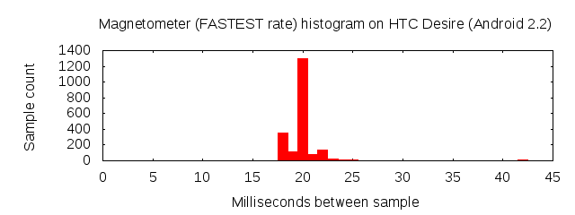
We can see here that almost all the samples come in at between 18ms and 25ms. There are a few outliers going all the way up to 45ms but there numbers are so few we can ignore them. This means we are limited to a maximum of a 40Hz sampling rate. If we drive the coil with a digital IO line that immediately caps our maximum bandwidth at 40bps.
But does the magnetometer respond quickly enough?
This Arduino sketch energizes the coil with a square wave of starting at 500Hz and decreases to about 1Hz over a few seconds.
int i;
int d = 1;
void setup() {
  pinMode(13,OUTPUT);
}

void loop() {
  for (i = 1; i < 500; i+=d) {

    // Increase increment as frequency decreases
    d = (i>>6) + 1;

    digitalWrite(13,1);
    delay(i);
    digitalWrite(13,0);
    delay(i);
  }
}
Here is the magnetometer data:
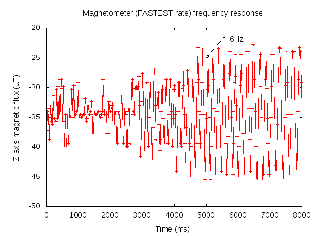
As expected high frequencies (on the left) are not be detected. It seems that we only get good pickup when the frequency drops to about 6Hz!
For encoding I'm going to use NRZ (non return to zero) similar to that used in RS232 with a bit period of 140ms (about 7 bps). The Arduino's UART lower limit is 300bps, so I can't use it to generate the signal. So I'm going to 'bit bang' the signal in software. Likewise, on the Android I'm going to have to decode in software also.
#define BIT_DELAY 140

int i;
char *text = "Hello World! ";

void setup() {
  pinMode(13,OUTPUT);
}

void loop() {

  char *s;
  s = text;
  while (*s != 0) {
    transmitByte(*s++);
  }

  delay (BIT_DELAY*10);
}
/**
 * Bit bang a byte
 */
void transmitByte (byte c) {

  // Start bit
  digitalWrite (13,1);
  delay(BIT_DELAY);

  // Data bits
  for (i = 0; i < 8; i++) {
      digitalWrite (13, ( (c&0x80)!=0 ? 1 : 0) );
      delay(BIT_DELAY);
      c <<= 1;
  }

  // Stop bit
  digitalWrite (13, 0);
  delay(BIT_DELAY);
}
Here it is in action:
The Android source is available here.
Potential improvements
My simple example uses a digital IO line to drive the coil. The Android magnetometers typically have at least 8 bits of resolution per channel [2]. It may be possible to squeeze another few bits per symbol by driving the coil with a DAC [3]. For example, 4 power levels can be used to encode 2 bits per symbol. The odd bit error can be corrected using forward error correction.
Also the magnetometer has three channels (X,Y and Z). It may be possible to construct a set of coils that excite the X,Y and Z channels independently … multiplying bandwidth by a further x3. Another thought: I've only discussed digital communication with the Android. Some applications might only require an analog signal.
These ideas are left as an exercise for the reader, but I’d love to hear how you get on if you try it.
Footnotes
[1] Googleing "Arduino pin 13", one is lead to believe there is a current limiting resistor in series with the MCU pin. However looking at the schematics, the tap for the pin 13 header comes *before* the resistor: so the resistor does not limit current. I only discovered this at the end of the experiment while proofing this post. Omitting the resistor did me no harm, but would advise to include the resistor to be safe. We need as much current as possible (more current means more magnetic flux in the coil). The Arduino Duemilanove datasheet specifies a maximum draw of 40mA on a IO pin, so 120 to 150 ohms should do the trick. If you need more current you'll need to use a transistor.
[2] The HTC Desire uses a AKM Semiconductor AK8973 3-axis magnetometer which uses a combination of a 8 bit ADC and a 8 bit offset DAC to yield up to 12 bits of equivalent resolution spanning +/- 2000µT of magnetic flux.
[3] The Arduino does not have a true DAC, however DAC functionality can be achieved by passing the PWM output through a low pass filter.