Thursday, December 12, 2013

Heating a room for 8p a day with tea lights YouTube video analysis

This video was recently brought to my attention: 


My first thoughts were:

  • Oh god, another free energy / perpetual motion machine idea
  • Hmm: this guy seems to understand basic energy (given his observation that the computer contributed to the room heat budget)
  • He works for a boating magazine (those guys tend to know their basic science/math).
So looked I at the figures.

It seems he's taking about these tea lights: http://www.ikea.com/ie/en/catalog/products/50097995/

They're actually €2 here in Ireland (about 1.70 GBP).

Measuring some tea lights I have here (they can't be too different to those IKEA candles), the diameter is 39mm x 11mm high. That's a total volume of 1.314 litres of wax for all 100 tea lights. It's most likely parafin wax in those candles. The density of parafin wax is 900kg/m3 so that's 1.183kg of parafin wax.

Looking at the heat of combustion per unit mass  parafin wax and kerosene / heating oil are pretty much identical energy wise at 46MJ/kg [1]. So the tea lights represent 54MJ of energy [2].

Looking at the latest prices for heating oil (kerosene) in Ireland (December 2013) is €0.83/litre. The density of kerosene is slightly less than parafin wax at about 800kg/m3. So to get 54MJ of energy I'll need 1.479 litres of kerosene. That's €1.22 at current prices.

Which is almost identical to 1 GBP at the time of writing. So fuel wise, this is on par with home heating oil (at the time of writing).

So what's with the flower pots? From a basic physics point of view there is no energy advantage here that I can see. But what it does do is contain the flame and make the apparatus safer than naked flame.

Conclusion:

Tea light candles are handy, store well and don't spill. They are also (probably) safer than liquid kerosene. At 1 GBP it's on parity with home heating oil for energy/cost. At the €2 price it's not quite as efficient as heating oil, but still in the same ball park. There might be a CO risk for small poorly ventilated spaces... but I guess no different to that of candles. Ok.. there might be something to this after all.. but it's no energy miracle.

[1] http://en.wikipedia.org/wiki/Heat_of_combustion

[2] Burning stuff is a rather efficient way of releasing energy. You'll get pretty much every scrap of that in heat.


Saturday, August 31, 2013

Using Sox spectrogram tool to analyze audio noise

While out on a walk near Lagos (Algarve, south Portugal) I noticed a loud buzzing/crackling sound. It sounded very similar to the kind of buzz/crackle you'd hear near high voltage transmission lines, but there was no power lines in sight. So I though I'd capture a few seconds of audio with a voice recorder app on my phone and look at the spectrum later to rule in/out an electrical origin: any thing electrical would have peaks at exactly 50Hz and harmonics of 50Hz.
It turns out that sox has a neat tool to create a spectrogram from any audio file:

sox recording.wav -n spectrogram -o spectrum.png

However the frequencies I was interested in were down well under 1kHz, so I first resampled at a rate twice the highest frequency of interest:

sox recording.wav -r 2k -o t.wav
sox t.wav -n spectrogram -o spectrum.png

So this is the result:


The buzz sound can be seen in the spectrograph as horizontal streaks at about 60Hz and 120Hz. Not being exactly 50Hz rules out an electrical origin. The frequency can also be seen to vary a little with time.

Here is a spectrogram of another recording I took on the way down to the beach later. There was multiple sources in this recording (audio file here) but fainter/further away.


and other (audio file here):


You can see multiple horizontal streaks  of varying frequencies.

Conclusion:

It's clear now the noise is from an insect. What insect, I have no idea. (Update: I think it might be Cicada)

If puzzled about the origin of a strange sound, record it and create a spectrogram... it might yield clues. Anything relating to utility power will be at the AC frequency (50Hz most of the world, 60Hz US).

Wednesday, August 28, 2013

LPC800 Mini Kit sous vide cooking controller

Summary

This project uses a LPC800 Mini Kit evaluation board as a sous vide cooking controller together with a DS18B20 temperature sensor and a modified timer unit and a rice cooker. A simple user interface (using just one microswitch and one LED) allows the user to select a set temperature. PID control and other techniques are used to heat and maintain water at the set temperature. An optional computer attached via a serial port captures debugging and temperature logging data. The firmeware source is open source and is available on GitHib. A video overview of the project is here.

Introduction

NXP sent a free LPC800 Mini Kit board a few weeks ago.  As part of the promotion they are running a "LPC800 simplicity challenge"... for weird and wacky apps using the LPC810 (open until end August 2013). This is my entry for this competition.

The LPC810 comes in a 8 pin DIP package of which two pins are reserved for power and ground. It costs about $1 in single quantities and that price drops to less than half in large quantities. The LPC800 Mini Kit board features this LPC810 but also a side connector for a serial port, two micro switches and a blue LED as well as some prototyping space.

I've been experimenting with sous vide cooking recently. This is cooking technique were meats and vegetables are sealed in a vacuum packed bag and slow-cooked in a bath of hot water at a very carefully controlled temperature. In this application temperature accuracy and control is paramount. For example: when cooking beef steak, the difference between a rare and a well done steak is just 5°C (10°F) (from 55°C to 60°C). Moreover if the water temperature is under 50°C (120°F) bacteria can multiply raising food safety risks.

Any appliance that heats water electrically can (in theory) be converted into a sous vide cooker. My choice was a 400W rice cooker which was on special at Lidl a few weeks ago (for €20?). The sous vide controller measures the temperature of the water and toggles the state of the heating element to precisely (and accurately) control the water temperature.

I used a hacked mains timer unit for the element control. I removed the user interface components of the device and broke out the low voltage relay control line. I've written about this in a previous blog post. For electrical safety I electrically isolated this with a Lite-On LTV-817S opto-isolator.

My first attempt at water proofing a DS18B20
temperature sensor.
For temperature sensing I used a DS18B20 digital temperature sensor. This is a three lead device (TO-92 package) which requires just one digital IO line to operate (the other to leads are for power and ground). The choice of a digital sensor avoids the need for analog to digital conversion (the LPC810 has no regular ADC capability). Water proofed probes using this sensor exist and I have one on order, but I'm not expecting it to arrive for a few weeks. So I improvised my own water proofed probe.

My first attempt involved a small section of PVC tubing. I injected silicon bathroom sealant into about 5cm (2 inch) of tube and then shoved in the sensor soldered to a 1 meter length of cabling. It's important that all the exposed metal is enclosed in the sealant. Failure to do so will result in the rapid corrosion of the sensors leads due to electro-chemical effects and a failure of the sensor in a matter of hours.

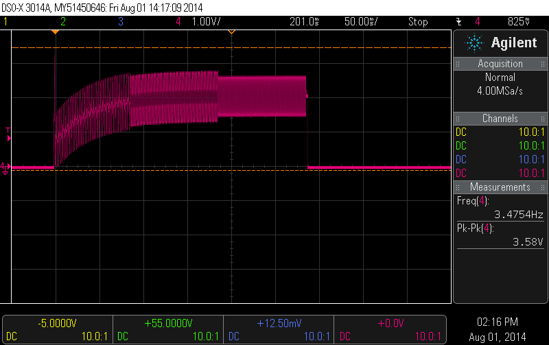
The water proofing worked, but the performance was terrible. Its performance was measured by allowing the sensor to cool to room temperature and then dunking it in hot water. The resulting exponential curve as a result of the step function of being dropped into water reveals the sensors 'time constant'. Using curve fitting this was found to be 67 seconds.


My second attempt at making a water proof DS18B20 involved soldering it to 3 wires of ribbon cable, then dunking that into a tube of silicone sealant so that the sensor and the exposed metal was well covered. I cut of the sealant at the very top of the sensor so that the top of the DS18B20 package was exposed directly to water. This worked much better with step time constant of just 13 seconds.


User interface

I was very limited in what I can do for the user interface (UI)  because the LPC800 Mini Kit has just one user LED (blue) and two microswitch. One switch I need for reset,  so that leaves just one switch and LED available. I could of course add extra hardware communicating SPI or I2C, but for this challenge I wanted to restrict myself to only the hardware available on the LPC800 Mini Kit. Also with just 4kBytes of program memory, there is little space to implement a complicated UI.

My temperature range of interest is from 55°C to 60°C for cooking beef steak. So I took advantage of that narrow range in the UI design. The operation is actually quite simple: After reset the user presses the switch marked "ISP" once for each degree over 54°C. So, for example, for a set temperature of 57°C three button presses are required. After a brief pause the LED will blink back the selection.

At any time during normal operation the user can query the temperature of the water by pressing the ISP button. The temperature will be read back by blinking the LED. There will be two sets of blinks with a pause between them. The first set reads out the temperature and the second set the units. So 54°C will be 5 blinks, pause, then 4 blinks. A zero digit is represented by one very short blink.

Temperature Logging

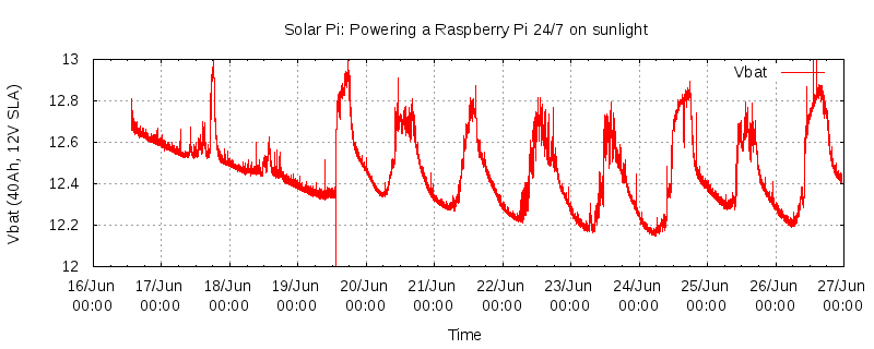
Debugging information and temperature logging data is sent using the LPC810's built in UART (serial port). An optional connected computer can then be used to chart the data in real time. The serial port is also used to re-flash the firmware. Temperature can be charted using gnuplot using a simple script like this: [insert]

Temperature Control Algorithm

This is still a work in progress. PID (proportional, integral, differential) control is usually used in these applications. However I found that it was difficult to avoid an initial overshoot. So I started to experiment with a two-phase approach. The first phase is the warm up: a test heating with the element on for 90 seconds and measuring the temperature change as result of this. The remaining time can then be calculated to bring the water right up to temperature. The second phase hands over control to a PID algorithm.

An interesting limitation of the Cortex M0 / M0+ MCUs is the lack of hardware floating point support. With just 4kBytes of program memory linking in float point library is not an option.  So I've used fixed point to implement the control algorithm.


The firmware

I'm using LPCXpresso, although the code can also be compiled with the GCC ARM compiler for bare metal systems. The firmware is open source and is available here: https://github.com/jdesbonnet/LPC810_SousVide. It compiles to about 4kBytes, unfortunately leaving very little room for enhancement.

Power requirements

So far I've been using the serial cable linking it to the laptop to power the controller. However this could easily work off a battery.  The ARM Cortext M0+ is designed for super low power applications and in this application the unit spends much of it's time idle. The UI requires practically no power at all (the odd LED blink).  In the program space available I've attempted to apply simple measures to reduce power consumption. For example all timing, delays etc is accomplished with the SysTick timer and anytime the program needs to wait for an event I invoke the WFI (wait for interrupt) instruction. I am not using deep sleep / power down modes at this time.

Conclusions

The LPC800 Mini Kit makes a successful sous vide cooker controller. The user interface is basic but is simple to use and understand. There is just enough program space and plenty of SRAM to implement the UI, control loop and serial port logging.

Project risk assessment and disclaimer

There are two risks to be aware of if attempting a similar project: first there is a potential shock hazard in designing a switching unit to control the heating element. The second is a food safety: cooking meats at too low temperature (<50°C) will result in bacteria growth and can cause food poisoning. There are many of sources of information on sous vide cooking on the internet so do your research! I would recommend validating the set temperature with a second thermometer until the firmware has proved reliable. If you undertake this project, I take no responsibility for your actions.


Friday, August 2, 2013

Silvercrest (Lidl) TwinTalker 4810 446MHz PMR radio teardown

I picked up these  "Silvercrest" (Lidl) brand TwinTalker 4810 446MHz PMR (private mobile radio) which are on special at Lidl right now. ("Silvercrest" is a Lidl own brand,  Topcom is the manufacturer of this device).


This PMR set peaked my interest because of the external mic/headphone socket. I have the idea that perhaps these could be adapted to packet radio without any need to hack the hardware (I find these radios handy on occasion, so I'd prefer to also keep them functional as walkie-talkies).

There was a time when devices like this came with full schematics and a service manual. Sadly, nowadays, you have to figure out everything for yourself (unless someone else already has!).

Opening it doesn't take much effort. Two screws in the battery compartment and two screws covered by rubber bungs near the top.


The first thing I noticed was the 56 pin SOIC IC at the bottom of the board. This is a Matsushita AN29160AA transceiver chip which deals with most of the radio protocols details. Excerpt from the datasheet:

"AN29160AA is IC for Transceiver. One package involve four systems about IF, PLL, Regulator, and AF. Involving 1st IFamp, 2nd Mixer, 2nd IFamp, FM-Detector, 460MHz PLL, Regulator for RXRF/ TXRF/ VCO/ MCU, OPAMPs for filter and Speaker Amplifier."


Also on that side of the PCB is a Z324 quad low power op-amps IC,  and a 2kBit K24C02C serial EEPROM which I guess is used to preserve radio settings across power cycles. The radio module and RF power amp is in a metal can along the edge of the PCB (bottom of photo above).

To view the underside of the PCB, I found that I needed to remove a blob of glue which fixed the helical antenna to the case. I was then able to pry up the PCB enough to take photos. (To remove it fully I would have had to snip the speaker wires, and I wasn't bothered enough to do that).

On the underside there is the LCD in a metal case. I assume the MCU is also in that area. There are pads for the user interface rubber buttons. Next to the button pads is a test pad which could be used to solder a breakout wire. As I want to keep this functional, I'm not going to tear down any further... besides from experience, there isn't much that can be done with the MCUs on consumer devices. The test pad labeled "TX MOD" does make me curious though...

Best I can tell the CFWM 450HT is related to driving the peizzo speaker. Next to that a crystal can marked 21.7 (MHz?). The marking on the speaker is "JW 16Ω 0.5W".


The supplied headphones use a 3 pole 2.5mm audio plug and comprise a single ear piece and a pod with a mic/push-to-talk button.


Best I can tell so far: the plug tip is for the mic and push-to-talk switch and floats at about 2.4V, the middle ring of the plug is audio out for the ear piece. When no transmission is received it's at 0V, when a transmission is received it jumps to 2.2V with the audio signal superimposed. Last ring is ground.

Measuring the resistance of the mic line of the headset to ground I see that the resistance is 3k when the PTT switch is open and drops to 1.1k when the PTT switch is pressed/closed.


Update (1 Aug 2014): I got back to looking at interfacing this PMR to a microcontroller and took another look at the headset interface (the 3 pole 2.5mm jack socket at the top).  I shall refer to the 3 lines as Tip, Middle and Sleeve.  I still haven't figured it all out yet, but these are various measurements I've taken while the headset is connected.

  • Tip-Sleeve resistance with PTT switch off: 2.9k
  • Tip-Sleeve resistance with PTT switch pressed (on): 1k
  • Middle-Sleeve resistance: 36 ohms (PTT switch has no effect)
  • Tip-Middle resistance with PTT switch off: 2.8k
  • Tip-Middle resistance with PTT switch pressed (on): 1.1k
  • Voltage of Tip relative to Sleeve with PTT switch off: 2.45V
  • Voltage of Tip relative to Sleeve with PTT switch on: 1.25V
  • Voltage of Middle relative to Sleeve with nothing being received: 0V
  • Voltage of Middle relative to Sleeve when receiving: 2.0V with audio out overlayed.

I also verified that shorting Tip to Sleeve via a 1.8k resistor will cause the unit to 'key up' and transmit (this was done with the headset disconnected). I found that the value of resistor is important. a 1k would cause the unit to only key up momentarily: the 1k resistor caused the Tip voltage to drop to about 0.9V which I guess is too low.

Here is scope trace from Middle (relative to Sleeve) when I key up and release. The waveform is the end-of-transmission bleep.


So in summary:

  • Sleeve is ground.
  • I can detect if there is an incoming signal by looking at the Middle DC offset. A value of about 2.5V indicates reception in progress. The AC part of the Middle is the received audio. Audio peak-to-peak voltage is about 1.5V at full volume.
  • I can cause the unit to transmit by dropping the Tip voltage to about 1.25V (eg shorting through a 1.8k resistor)
  • Still to do: interfacing a MCU DAC output to the audio in.
I'll update as I find out more.


Sunday, July 28, 2013

Silvercrest (Lidl) EIM-804 'digital weekly timer' teardown

I purchased up a few Silvercrest brand EIM-804 'digital weekly timer'  from Lidl two years, with some sort of hackery in mind. And finally I found a use for one. So I tore one apart.


There are two PCBs: one on the bottom which deals with power related matters and one attached to the top lid which is the user interface (UI). The PCBs are connected with a 3 wire ribbon cable.

The power board comprises a fuse, mains relay, relay drive circuit and a low voltage (1.2V) power supply and backup battery (cell) for the user interface board.


The UI board comprises an application specific Chip-on-Board (COB) IC, a custom LCD mated to the PCB by a zebra strip and contact pads for rubber buttons. It's connected to the power PCB by a 3 wire ribbon cable. Two wires for power (1.2V) and one (labeled 'D' on the PCB) for relay control. I found if this was left floating the relay was on and if I drive it to 0V the relay was switched off.


There isn't much that can be done with the UI board and the application I have in mind will require a separate MCU to control the relay. So I unsoldered the ribbon cable from it.

I am hoping to use the low voltage power supply to power my application. So I took a shot at reverse engineering the schematics of the power board:


So it seems there are two DC power rails: a 24V rail set by zener diode DZ1 (a 24V 1N4749A) which together with Q1 is used to energize the relay coil. A second power rail is derived from the 24V rail and is set by DZ2 and provides 1.2V for the UI PCB and the 1.2V backup battery.

The relay is controlled by line D. It's interesting to note that the Q1 (a SS9014 NPN) is a high gain transistor, so it doesn't take much base current to cause the relay to activate.  If D is left to float then the small current that flows through R4 (about 73µA) is enough to activate the relay. If D is driven to 0V then that current is directed away from Q1 causing the relay to deactivate.

D2 is the usual fly-back diode which absorbs the voltage spike due to the sudden interruption of current through the relay coil. Diode D1 protects Q1 (and the driving logic) from excessive current if D line is high.

The purpose of D3 (I guess) is to prevent the 1.2V battery from draining through EC2 etc when the device is unplugged.

One important observation about the 1.2V low voltage rail: the 0V is not ground. It will vary between 0V and +24V relative to the ground/neutral line. Therefore you must optoisolate it if interfacing to external circuitry. The following is a scope trace from the 1.2V line on the ribbon cable. Connecting this to external (grounded) logic devices is likely to damage it.


So my plan is to use this device with the UI PCB removed and a Lite-On LTV-817S opto-isolator with the output connected to the D and 0V line of the ribbon cable. The relay will be on by default. Passing a current through the isolator's input LED will cause the relay to switch off.  More on this another time...


Friday, July 26, 2013

DIY thermal labels

My thermal label tape cartridge for my Brother P-touch 65 label printer recently ran out, and I was horrified at the cost of a replacement cartridge – almost the cost of the printer itself (which includes a label cartridge!).

So I tried a little experiment one night to see if I could make this thermal label tape myself. I have loads of rolls of thermal paper from some prototype work I was doing a few years ago which involved a thermal printer. So I took a about 1m of thermal paper and using a ruler and box-cutter cut it into (approx) 9mm wide strips. Next I opened the tape cartridge (it wasn't too difficult ... no tools needed... but be careful not to break it).


I used a bit of sticky tape to mate my new thermal tape to the spool. It's important to note which is the top surface of the thermal paper (btw: I have it the wrong way up in this photo!).

I spooled the tape, closed the cartridge case and put it into the printer.

The first try wasn't very successful.  The cheap thermal paper I used is quite thin and the capstan roller wasn't getting enough purchase on the tape to pull it out of the cartridge: [1]


By gently pulling the tape while printing I managed to get a clean print.  But the other problem was the paper was facing the wrong way, so the print was a mirror image of what it should have been:


Then I remembered I had a roll of high quality (thicker/heavier) thermal paper. So I tried that, got the orientation right and finally got a good result.


Am I going to use this hack? Probably not. A few problems: First it's rather labor intensive cutting the strips and spooling it up. Second there is no sticky surface... so you'd need to glue this on to whatever you're labeling. Also regular thermal paper doesn't age well when exposed to the elements ... it's likely to fade in less than a year, especially if exposed to direct sun light. But I thought it was still interesting enough to write up on the blog.

Foot notes

[1] The capstan roller is squeezed against the paper when the printer lid is applied. A wedge on lid squeezes the roller against the paper. It's possible that additional pressure can be applied to the paper by widening that wedge (eg by adding a few layers of duct tape).

Tuesday, July 23, 2013

Offline YouTube videos on your Android mobile device

So you going somewhere with time to kill, but with slow internet, or no internet. There are many YouTube videos you'd like to watch.... but can't.

It's a common problem while travelling or on vacation. There are many solutions. Here is my solution. This is for Linux people with an Android mobile device who are running a Linux computer somewhere (home, office, in the cloud, or a Raspberry Pi).  I'll refer to this computer as the 'server'.

So the idea is I use Bit Torrent Sync to communicate between the mobile device and the server. BTSync is handy because it's peer-to-peer and doesn't require any firewall configuration.

  1. Install Bit Torrent Sync on the server and run it (you'll probably want to configure the server to start this automatically on boot).
  2. Create a directory and generate a shared key for the directory. 
  3. Install Bit Torrent Sync for Android on the mobile device
  4. Create a directory and assign the key created in step 2. You can do this using QR codes.
  5. Install a simple text editor app on the Android device if you don't already have one. I use Jota.
  6. Download and install youtube-dl tool on the server if you don't already have it.
  7. Download the youtube_fetch_daemon.sh script. Review it and satisfy yourself it does what you expect it to (it's less than a screen of code). Then run it and let it continue to run. Or set it up to start on boot.
So let's say you're in an airport waiting to board. You have access to moderate WiFi, but would like to download a few videos to watch on the flight. This is how to do it:

  • Navigate to the video in the YouTube app.
  • From the menu chose 'Copy URL'.
  • In the Android text editor paste the URL and save the file as a .txt file in the directory created in step 4. This file will now transfer to your server and will cause that YouTube video to download.
  • After allowing a suitable amount of time (depending on the quality of the connection on the server and the size of the video), use the BTSync app to view remote files. If you see the video there, touch that video and it will start to download to your device.
  • Use your video player to play off local storage.
Edits:
28 July 2013: Link to youtube_fetch_daemon.sh script fixed.

Tuesday, July 9, 2013

The effect of temperature on the efficiency of photovoltaic panels

A few years ago while arguing about the economic viability of photovoltaic (PV) electricity in Ireland I learned that the ambient temperature can have a significant impact on the performance of the PV panels and it is an important variable in return-on-investment calculations. The lower the temperature the more efficient the panels. [1]

Today we have a rare heat wave in Ireland, so I thought it was a good time to see this effect for myself. I recorded the experiment on video. What I've got here are 2 x 15 watt peak (rated) panels charging a 40Ah sealed lead acid (SLA) battery and a Raspberry Pi [2]


Conclusion

At the start the panels were reading 55°C (read from a non-contact thermometer) and were delivering 710mA of current to the battery/Pi system. After pouring water to cool the panels the temperature dropped to 42°C and the current rose to 820mA. I'm going to use current as a measure of efficiency here [3]. So that's about 14% efficiency increase for a 13°C drop in temperature.

Footnotes


[2] It's a Raspberry Pi Model A (the one without ethernet or inbuilt USB hub). I've got an external unpowered hub connected to the model A's sole USB socket and to that a WiPi WiFi dongle and a Arduino Leonardo.  A 12/5V DC/DC car converter down converts the 12V to the 5V required by the Pi. The current draw from the Pi at the 12V end of the converter is 210mA.

[3] Measuring and extracting power from photovoltaics is not a trivial topic.

Thursday, June 27, 2013

Solar Pi

2 x amorphous silicon 15Wp panels
(Make/brand is IPC Global Battery Saver Pro)
About 10 years ago when Maplin opened a local store, I picked up some solar PV panels, a 40Ah sealed lead-acid (SLA) battery and a charge regulator on special. For the past 10 years these panels have been sitting in a window in my guest room doing nothing but keeping my battery nicely charged.

Finally, I've put this setup to some better use. I'm experimenting with the idea of keeping a Raspberry Pi powered 24/7 using nothing but PV panels and a battery. I'm based in Galway, Ireland (53N, 9W) and here we don't get too much direct sun (clouds keep getting in the way :)... so this goal isn't completely trivial.

My setup so far: 2 x 15W-peak amorphous Silicon panels (300mm x 1000mm) usually laid flat on the ground. A 12V lead acid battery charge regulator, a 40Ah SLA battery. The charge regulator's function is to stop charging the battery when the battery reaches 14.2V.

So I have a nice 12V DC power supply from the battery. But the Raspberry Pi requires the standard USB 5V. A linear regulator could do the job but would be at best only 42% efficient (5V/12V). Instead I'm using a low cost USB car charger (listed as a recommended Pi accessory at Farnell / Element 14, SKU 2113630, cost about €5). This is a DC/DC switch mode converter.  I don't have efficiency figures for this, but I suspect it's somewhere in the 80% efficiency region.  Update: 2 July 2013: I've measured this to be 73% [1]

Low cost 12V to 5V (USB) DC/DC
converter available from Farnell
(SKU 2113630)
I chose a Model A Pi because it uses significantly less current than the Model B (due to the missing USB hub / ethernet interface chip). The down side is I need a USB hub if I want to connect more than one device (which I do!). I'm using a low cost "Technica" brand USB (unpowered) hub from Tesco. For networking I'm using the WiPi WiFi USB dongle (Farnell SKU 2133900).

I want the Pi to be able periodically log the battery voltage. Unfortunately the Pi doesn't have an ADC, so it's the Arduino (Leonardo) to the rescue, connected to the Pi via the USB hub.  But... the Arduino ADC only handles 0 to 5V, so a voltage divider is used to bring the maximum possible battery voltage (about 14V for 12V lead acid battery) into the 0 to 5V ADC range. I'm using a 39k/12k divider bringing the 0 to14V range down to 0 to 3.3V (I had originally planed to use a 3.3V logic board you see!).

My experimental setup. The yellow device (top right) is the battery charge regulator. The PV panels are outside in the garden.

Note there is a trade off in the choice of resistor values: you want them much lower than the impedance of the ADC input, but remember that current continuously flows through this divider, so if you make them two low you'll drain the battery! In my case the current is V/R = 12V/(39k+12k) = 0.24mA: an insignificant line item in the power budget. And those values are low enough for use with the Arduino [2] [3].

My original strategy was to take one ADC value and echoed it to the serial port, pause for a few seconds and loop. But I found the data was very noisy. So instead I wrote this Arduino sketch:

void setup() {
  Serial.begin(9600);
}

void loop() {
  uint64_t a=0; // Need 64 bits due to size of sum
  int i, n = 1<<14;

  for (i = 0; i < n; i++) {
    a+=analogRead(A0);
  }

  Serial.print((int)(a>>10));
  Serial.print ("\n");
}


So I sum 16384 (2^14) ADC samples, but divide by 1024 (2^10). This is ADC oversampling and not only smooths out the noise in the signal, but gives me extra bits of ADC resolution! [4]

So my battery voltage under load (Vbat) vs time chart looks like this:


The goal here is to always keep the battery voltage under load over 12.1V (which I'm estimating to be about the 50% discharge point). [5]

For the first two days I had the panels indoors against the window. I was losing about 0.1V at the end of each day: clearly not sustainable. So I moved the panels outdoors, and this looks a little better. On days 19 June to 23 June (cloudy days with a little hazy sun) I'm losing 0.05V/day. But 24 June and 26 June were sunny and resulted in a net gain in battery voltage.

So the conclusion so far: if we had sunnier weather in Galway this setup would probably provide sustainable 24/7 power to the Raspberry Pi, at least during the summer months when the days are long. But realistically that isn't going to happen. Also in a few months the days will get shorter and the sun lower on the horizon so the available power budget will be greatly diminished. I'm not going to invest in more PV panels, so therefore I need to find ways to shed some load. Hopefully I'll follow this up with a Part 2 in a few weeks.

Footnotes:

[1] I did a quick measurement of the efficiency of the car USB charger adapter using a 10Ω resistor as a dummy load. The input (at 12V) was drawing 244mA and the output USB 5V was drawing 426mA. So the efficiency is (5 * 0.426) / (12 * 0.244) = 73%. When connected the the Raspberry Pi, hub, Arduino and WiPi I measure a mean current of 212mA  entering the 12V side of the DC/DC converter. The (approximate) efficiency of a linear regulator is Vout/Vin.

[2] The Arduino (Uno, Leanardo etc) ADC impedance is often quoted as 10k. But that's a worst case scenario where you may be using several different ADC inputs with substantially different voltages. If you're continuously sampling something close to a DC voltage (as is the case with a battery) the impedance is more in the megaohm region.
http://forum.arduino.cc/index.php?&topic=116491.msg876799#msg876799

[3] For ultra low power applications a FET transistor could be used in series with the voltage divider to switch it off when not needed.
http://www.microbuilder.eu/Tutorials/Fundamentals/MeasuringBatteryVoltage.aspx

[4] See this link for an app note on ADC oversampling:
http://www.atmel.com/Images/doc8003.pdf

[5] Information about a 12V lead acid battery:
http://en.wikipedia.org/wiki/Automotive_battery

[6] Note on 'noise' in ADC signal. Actually this is mostly due to power fluctuations in the Pi (and peripherals). I notice a small spike each time I copy the the ADC log file over the network. Or if I run any CPU intensive task. Interestingly, Vbat appears to increase when drawing more current. This is because the additional current causes a small sag in the 5V supplied to the Arduino. The Arduino is using the 5V supply as the reference for the ADC. A small sag in the reference voltage means a higher ADC reading given the same battery voltage.

Other notes:

Similar projects:

Thursday, June 13, 2013

Using a powered USB hub to both expand the USB bus and power the Pi

While the Raspberry Pi is an inexpensive little computer, all the little accessories can add up. For many applications you'll need a powered USB hub to expand the number of devices that can be connected to the Pi. But you may also be able to power the Pi from the same hub, saving you from purchasing a USB charger. It tried this with the 7 port hub available from Farnell (SKU 2115058, €10) and it worked just fine with a Model A Pi. This compares favorably with a dedicated USB charger which typically costs €6 - €10.


Update (14 June 2013): It seems it's not even necessary to use the micro USB cable (at least in the case of this hub).

Update (19 June 2013): I just noticed that the possibility of powering a Pi from a USB hub that back feeds power was mentioned in the release notes for the Revision 2 of the Rapberry Pi hardware. This is made possible by the removal of the USB port poly fuses that were present in Revision 1 hardware. However it does note that the hub must not supply more than 2.5A under fault conditions (presumably because there is no over current protection supplying power this way).

Tuesday, April 23, 2013

Measuring the alcohol content of homebrew wine

A little over a week ago I started a batch of 3 week wine (my first in about 15 years).  According to the instructions (Cabernet Merlot "California Connoisseur" brand)  most of the fermentation takes place in the first week. But I was surprised that all airlock activity ceased after day 6. I really thought the airlock bubbling would decay exponentially over the 21 days or so.

Checking a sample with a hydrometer the specific gravity was 0.992 which is well in the range of a fully fermented wine. It also smelled and tasted like wine, and after drinking the 100ml sample... felt like fully fermented wine also!

However to gauge alcohol content I needed the pre-fermentation specific gravity reading, which I never bothered to take.

Instead I came across an alternative method:

  1. Check that the specific gravity of your tap water is exactly 1.000. If not you will need distilled or rain water.
  2. Take a small sample of wine (I used a 100ml graduated cylinder) and measure the specific gravity, SG1. This was 0.992 ± 0.001 in my case.
  3. Then transfer to a pot and boil off about half of the liquid. This ensures that all the alcohol is boiled off. I noticed a distinct change in odor after a few minutes of boiling... from a strong alcohol smell to a sweet odor.
  4. Allow to cool (hydrometers are normally calibrated for room temperature)
  5. Pour back all the liquid back into the graduated cylinder. In my case this amounted to 45ml.
  6. Top up with water back to the original 100ml mark.
  7. Measure the new specific gravity, SG2. In my case it was 1.008 ± 0.001.
To calculate alcohol content, use the following formula [1] :

SI = (SG2 – SG1)*1000

%ABV = (0.008032927443 * SI^2) + (0.6398537044 * SI) – 0.001184667159

So in my case that's SI = 16 ± 2, %ABV = 12.3% ± 1.8% which is a reassuring result, except the error bar is very large. Must see if I can get myself a narrow range hydrometer and repeat with more accurate specific gravity measurements.

Now, here is the interesting bit for me: where does this formula come from? The source at [1] is vague on that. When I try to derive a formula from first principles, I get %ABV = 100*(SG2-SG1)/0.211 which is also mentioned in [1] and said to be wrong. I'm also suspicious of the large number of significant digits of the coefficients. I'm wondering is this just a curve fit of the table in [2]?

If anyone has any insights, please post a comment below.

Update: after some more googling, I see that my attempt at deriving a formula from first principles was assuming that say 80ml water + 20ml ethanol would result in 100ml of liquid. This is not the case with water + ethanol. This may explain the quadratic term.

Thursday, February 28, 2013

Dangerous Prototypes QFP breakout board tips

Today was my second attempt at using the Dangerous Prototypes QFP 0.5mm pitch breakout board to solder  LQFP-64 IC.  My first attempt was messy due to a slight misalignment of the pins. Today's attempt was more successful.

Almost everyone agrees the general workflow is to tack down two opposite corners with a soldering iron and when alignment is verified use your favorite technique to solder the remaining pins in place. But getting the IC perfectly aligned (and keeping it there while tacking the corners) is tricky.

Two things I figured today:

1. The solder mask can act as a physical alignment guide. Put the IC approximately in place and then firmly push down on the IC and attempt to slide it up and left (assuming the normal orientation). You'll find that when the IC's pads reach the solder mask there is resistance to this sliding motion. At this point the IC should be perfectly or nearly perfectly aligned. [Update 4 Mar 2013: this worked just fine with an Analog Devices ADAS1000 but I just tried this with a smaller 32 pin package and noticed the IC's pads were shorter so this tip didn't work: so this is very much package dependent.]

2. Next while keeping the IC pinched firmly in place I used a washing line peg to clap it in this position. I found the peg applied enough force to keep it reliably positioned, yet it was still possible to nudge it slightly should the alignment need adjustment.

I then tacked two corners, removed the peg and soldered the rest of the pins.


Wednesday, February 20, 2013

DeLonghi Cafe Treviso (BAR14F-E) Repair

(Note: I wrote this blog post back in February 2013, but for some reason never I published it. Fixing that now.)

In the last week my low cost coffee machine (DeLonghi Cafe Treviso BAR14F-E) clogged up. Turns out (as I suspected) it was a build up of limescale.  I’m writing this short blog post to aid anyone else who might have the same problem. I suspect many appliances like this are dumped and replaced, when a 1-2 hour repair is all that’s needed to prevent more e-junk entering the world’s landfills.


Usual disclaimers apply: this worked for me, if you try it yourself you do so at your own risk. If your device is still in warrantee  it most likely voids it. There are exposed live mains contacts all over the insides of this machine: disconnect before opening and use common sense.


I got some helpful tips from this write up. Not the same model, but there were several useful tips (eg using a regular flathead screwdriver to remove the security screws).

I suggest you photograph everything before disassembling. In that way if you can’t remember what goes where, you can refer to your photos.

Warning: this is a mains appliance. Inside there are many live contacts. Disconnect before opening (I suggest physically unplugging and keep the plug in view so that there is no doubt that it’s unplugged).

I originally hoped I could perform the entire repair by accessing from the top without removing the mechanism, but found during re-assembly I needed to remove the entire mechanism. So best do this from the start.

Remove the water reservoir.

The top and bottom covers use security screws Torx screws (T20H), however it seems a regular 2.5mm flat head will get sufficient purchase to loosen without causing any damage to the screws.

Remove the bottom cover. Remove the mains lead retaining clamp from the external case by sliding it down. This will facilitate separation of the mechanism from the case.

Remove the top cover. You will need to remove the screw covers (use a knife to pry open). You will also need to remove the steam valve by pulling upward (moderate force is required).

Remove the steam hose from the pressure vessel by clenching the retaining clip with a pliers.

Before this next step carefully note the positions of the electrical contacts to the switches (eg take a photo). Remove the contacts from the switches (some of the spade connectors have a tiny clip which you need to depress to remove). Remove the switches and the element indicator neon (that took a little bit of fiddling).

Remove 3 x cross head screws which secure the pressure metal chassis to the plastic outer case. At this point it should be possible to separate the mechanism from the case.

Remove the 4 x hex bolts which fasten both halves of the pressure vessel and secures it to the chassis. You should now be able to separate the top and bottom half of the pressure vessel. Clean out. Also clean the flow valve as described in Step 19 in this write up.

Reassembly is the reverse of what was just described. Take care not to damage the rubber seal between the two halves of the pressure vessel. If it gets dirty clean it before reassembling. Make sure the seal is good and tight.

Misc notes: There was a manky fiberglass wool like thermal insulator keeping the incoming mains wires separated from the walls of the pressure vessel (which I’m sure gets quite hot). Probably because of it’s age it was falling apart and quite dirty. I thought about using some cardboard instead, but because of the temperature and live voltage operating within mm of this I thought it was too much of a fire hazard. So I opted to leave out that insulator when I reassembled. I’m not sure this is a good idea, I guess I’ll find out soon.

Monday, January 7, 2013

Saving streams from the TG4 player

I notice that howto guides on doing this seems to change frequently. This worked for me in early January 2013 and will probably be out of date soon. I use Linux... but I'm sure these instructions can be adapted for other OSes.

You will need rtmpdump.

Open a decent modern browser (eg Chrome or Firefox) and open the developer tools. Monitor HTTP traffic with the tools while you open the program you wish to record. When the program starts you will see several GET and POST requests in the background. Look for a request which features a fragment that looks something like this:


mp4:videos/1290862567001/1290862567001_2032327037001_WCL016084-14-4.mp4


This will form the -y parameter of the rtmpdump command.

Also look for traffic going to a host that looks like cp156323.edgefcs.net. The host name part of that address may vary. Match the host name in the -r parameter to this host name.

 Now try this (making the adjustments mentioned above):


rtmpdump -r "rtmpe://cp156323.edgefcs.net/ondemand"  \
-y "mp4:videos/1290862567001/1290862567001_2032327037001_WCL016084-14-4.mp4" \
-o myvideo.flv

These instructions may also apply to the RTE player, but I haven't tried it.